|
|
||
|---|---|---|
| src | ||
| LICENSE | ||
| README.md | ||
| index.ino | ||
| unused_code.cpp | ||
README.md
Software Task 1
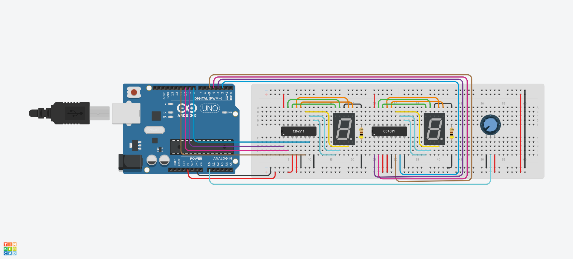
Hardware
The Arduino powers both CD4511 display driver chips with 5v. Each display chip is wired to a 7 segment LCD. The Arduino is connected to a potentiometer and reads its voltage from analog pin 0. The value read from the analog pin is then interpreted in software then sends out a signal to pins 2-5 and 8-11. The Arduino controls the displays using digital pins 2-5 to control the right LCD, and uses pins 8-11 to control the left LCD. The LCDs are common cathode displays. Each CD4511's a-g pins are wired to their respective a-g 7 segment LCD pins. The common pin (pin 8) is wired to a 400 Ω resistor which is then grounded.
Software
When the Arduino first receive power, it runs the function setup which takes note of the Arduino pins used. After the setup function finishes, the loop function runs indefinitely. Inside loop the voltage from analog pin 0 (ANALOG_PIN) is read.
analog_data = analogRead(ANALOG_PIN);
The potentiometer gives a variable value, that is analog_data, which ranges from 0 to 1023. This variable is then scaled by a factor of 10.23 (SCALE_FACTOR) which then makes the input range from 0 to 100 (scaled_data).
double scaled_data = (double)analog_data / SCALE_FACTOR;
We do not have to worry about values larger than 100 because the SCALE_FACTOR makes sure we never get any number bigger than 100. Since the 2 displays can not show a 3 digit number, if the input value is 100 make it equal to 99.
if (scaled_data == 100)
{
    scaled_data = 99;
}
Now split the digits of scaled_data into two separate variables (ones_digit & tens_digit) using the function split_digit. Each digit is then displayed using the function to_display. The to_display function takes a digit created from split_digit and the 4 pins you want to send the signal to as parameters. This function is run twice, once for each display.
void to_display(int num, int pin_1, int pin_2, int pin_3, int pin_4)
{
	switch (num)
	{
	case DPY_1:
		digitalWrite(pin_1, HIGH);
		digitalWrite(pin_2, LOW);
		digitalWrite(pin_3, LOW);
		digitalWrite(pin_4, LOW);
		break;
    ...
Reflection
This is my first time using an Arduino and programming in Arduino Programming Language *cough* C++ *Ahm*. I don't know C++ so I just wrote code as if it was C (and it worked!). The code controls both displays separately, however its possible to wire the displays in a way such that when the first displays passes 9 the next display increments by 1, I don't know how to do that though. I had some difficulty deciding how to control the displays because I think its probably possible to use a series of binary operations to control what LEDs are on within a display. If it's possible it would simplify the long switch statement in the to_display function. I would have put all of the variables and initialization in a separate header file however that was not an option in TinkerCAD.